| e-Trigger
4-Channel Encoder Trigger: 9...36V
Powered, Quadrature Encoder Interface for frequencies up to 1000KHz with 100Mbps Ethernet InterfaceeTrigger is an innovative system that allows the continuous monitoring of the encoder state and produce a trigger output at the exact encoder positions. Up to 4 separate encoder positions may be used for triggering purposes. It's a perfect solution for an automatic control of industrial and commercial machine vision applications. High speed communication is the key for a flexibility and efficiency. The ability of “on the fly” injections, gives the opportunity to reach the optimal performance and save your time for trigger configuration. The build-in processor is used to calculate not only the status of the encoder, but also the trigger point in advance*, depending on velocity of the motor. The Hardware supports up to 1000 KHz Encoder Frequency.
Typical Applications: - Time efficient industrial and commercial applications
- Vision solutions / camera trigger
- Motion control applications
Features: - Up to 4 Programmable triggers
- 4 maskable output channels for each trigger
- Selectable movement direction (forwards, backwards or both) for each trigger
- Ability to store the configuration into Flash ROM
- Support for high-speed encoders with operating frequency up to 1000KHz
- Realtime trigger position calculation depending on current motor speed
- Ethernet/UDP and RS232 communication interfaces
- Configurable trigger duration
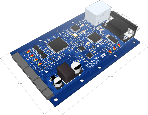
Mechanical & Electrical Specifications and Pinouts:| eTrigger Dimensions & Pinout | Schematic wiring of the channel output connectors |
|---|
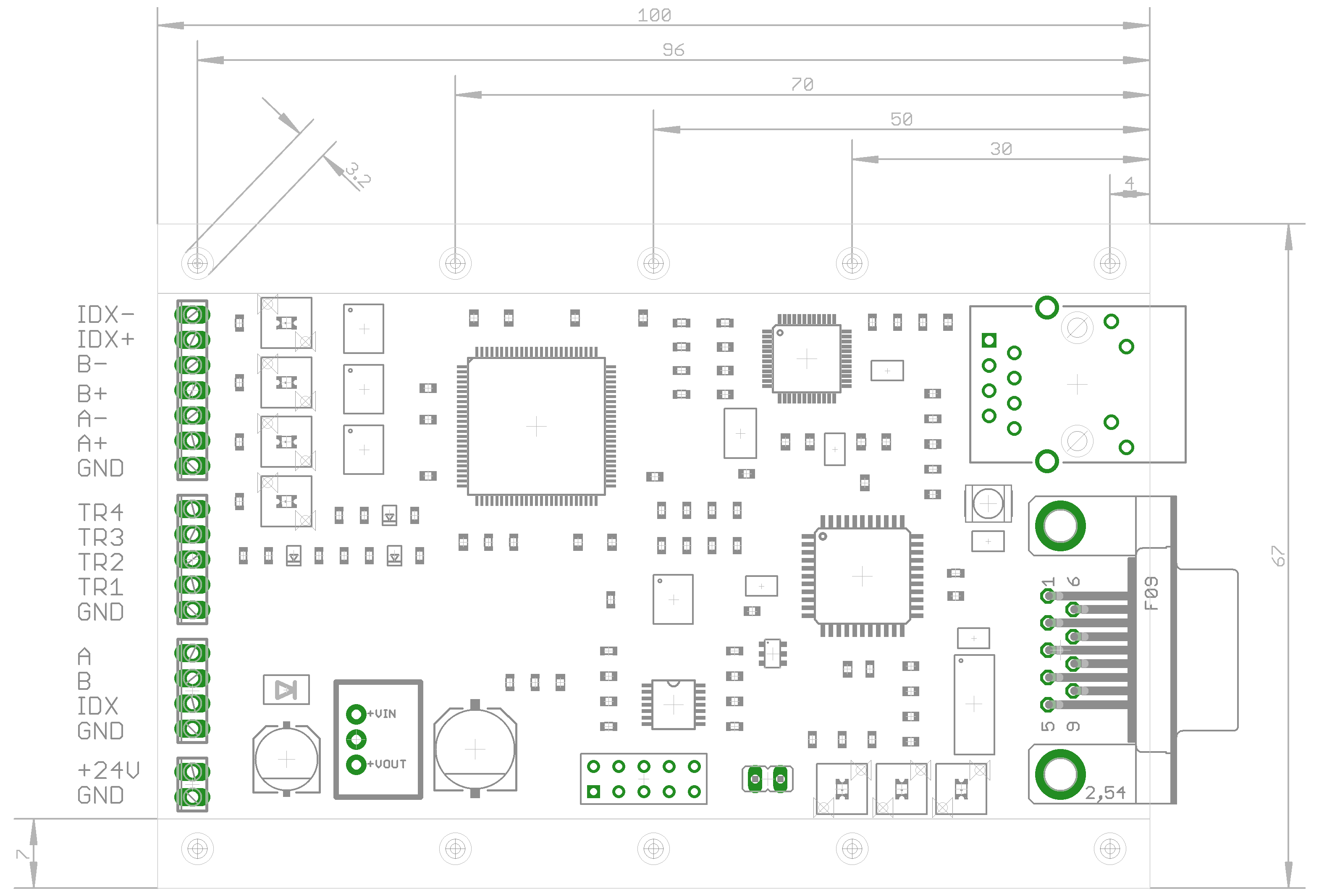 |  |
RS232 Pinout:| DE-9 pin | Signal Name | Description | Direction |
|---|
| 3 | RX | Data Receive | IN | | 2 | TX | Data Transmit | OUT | | 5 | GND | Signal ground | |
Channel Outputs:| Signal Name | Description | Direction | Voltage |
|---|
| TR1, TR2, TR3, TR4 (Channel 1....4) | Channel output | OUT | min: VDD-1V | | GND | Channel ground | | GND |
Encoder Pinout:| Signal Name | Description | Direction | Voltage |
|---|
| A- | Encoder Phase A- | IN | -7...+12V | | A+ | Encoder Phase A+ | IN | -7...+12V | | B- | Encoder Phase B- | IN | -7...+12V | | B+ | Encoder Phase B+ | IN | -7...+12V | | INDEX- | Encoder Phase INDEX- | IN | -7...+12V | | INDEX+ | Encoder Phase INDEX+ | IN | -7...+12V | | GND | Encoder Ground | | GND |
TTL Encoder Pinout:| Signal Name | Description | Direction | Voltage |
|---|
| A | TTL Encoder Phase A | IN | 0...+5V | | B | TTL Encoder Phase B | IN | 0...+5V | | INDEX | TTL Encoder INDEX | IN | 0...+5V | | GND | TTL Encoder Ground | | GND |
Power Supply:| Signal Name | Description | Voltage |
|---|
| VDD | Power supply | +9...+36V | | GND | Ground | GND |
Summary:| Supply voltage (VDD) | +9....+36 V | | Encoder input voltage (A±, B±, INDEX±) | -7...+12 V | | TTL Encoder input voltage (A±, B±, INDEX±) | 0...+5 V | | Trigger channels output voltage | min: (VDD-1V) | | Ethernet communication speed | 100 Mbps | | RS232 | 115200 bps, 8 bit, 1 stopbit, no-parity | | Max trigger reaction time | 10 μs (100 KHz) | | Max encoder frequency | up to 1000 Khz |
FIMC1 v3.0
Stepper motor controller with integrated motion controllerFeatures: - Two product versions: normal FIMC1V3A and extended FIMC1V3X;
- Up to 5A motor coil current, 2.5A per coil;
- Full, half, quarter, or sixteenth microstepping options;
- Motor power supply: operation over 12 to 50 V supply voltage range;
- RS232 serial interface (TTL) for the communication;
- Integrated motion controller;
- Velocity up to 105steps/sec;
- Acceleration and deceleration up to 105steps/sec2;
- Positioning, constant velocity, soft stop, halt operation modes;
- Position from –2147483648 to 2147483647;
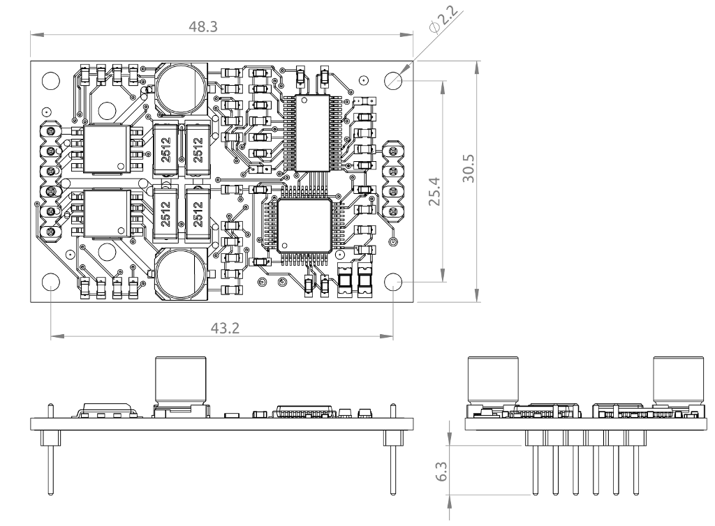
- Small module size 48.3mm x 30.5mm;
- Perfect for using in common Arduino applications;
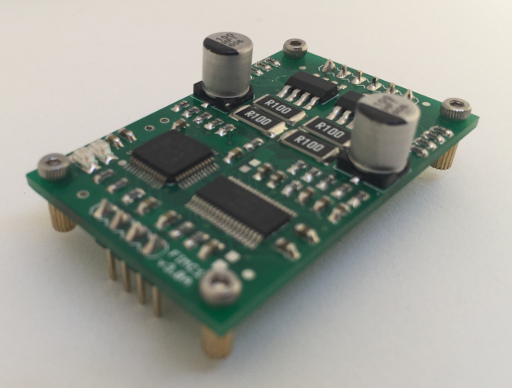
FIMC1V3A | 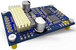
FIMC1V3X |
| | FIMC1V3A | FIMC1V3X |
|---|
| Max motor current per coil: | 1.5A | 2.5A | | Max motor current: | 3A | 5A | | Full step: | ⚫ | ⚫ | | Half step: | ⚫ | ⚫ | | Quarter step: | | ⚫ | | Sixteenth step: | | ⚫ | | Heatsink: | | ⚫ | | Motor operating voltage: | 12V .. 50V | 12V .. 50V | | Controller operating voltage: | 3.1V .. 3.5V | 3.1V .. 3.5V |
|
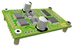
FIMC1V3A and FIMC1V3X board plan:
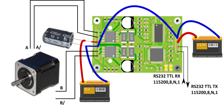
Schematic plan, typical application:
Communication protocolBaud rate 115200, data bits 8, stop bit 1, no parity bit: A command begins with instruction code and ends with a carriage return '\r' (ASCII 0x0D). Multiple commands can be transmitted with a semicolon as separator. For example, single command: 'help\r' or multiple commands 'ac=100;ac;dc\r'. There are 'read' and 'write' command types. 'Read' command only gets a value or parameter, 'write' command sets a parameter and shows a current value of the parameter in the response. For example, read command (get current acceleration): controller read command: 'ac\r' controller response: 'ac=1000\r' For example, write command (set current acceleration to 2000 steps/sec 2): controller write command: 'ac=2000\r' controller response: 'ac=2000\r' Commands overview(R=read command, W=write command): | command | R,W | description and examples |
|---|
| hp, help | R | display a help screen with a list of possible commandsno additional values; | | vr, ver | R | get current software versionno additional values;command: vr\r
response: vr=FIMC1-3.17.20.1\r | | rs | W | reset the device, all parameters will be set to default valuesno additional values;command: rs\r
response: rs=1\r | | mm | R,W | get/set current motor modeallowed values:
0=halt: if a motion is currently in progress (motor runs), it will be halted immediatly;
1=position mode: in this mode motor position can be controlled with tp (target position) parameter;
2=velocity mode: motor runs with constant velocity sp and rotation direction rd;
3=soft stop mode: if a motion is currently in progress (motor runs), it will be stopped with a deceleration dc;
command (read): mm\r
response (read): mm=0\r
command (write): mm=1\r
response (write): mm=1\r | | ms | R,W | get/set current microstepping resolution
allowed values:
1=full step (default);
2=half step;
4=quarter step (only FIMC1V3X);
16=sixteenth step (only FIMC1V3X);
command (read): ms\r
response (read): ms=1\r
command (write): ms=2\r
response (write): ms=2\r | | cp | R,W | get/set current motor position (position mode mm=1)
allowed values: –2147483648 to 2147483647;command (read): cp\r
response (read): cp=-321654\r
command (write): cp=987321\r
response (write): cp=987321\r
WARNING: if you change current motor position (cp) in position mode (mm=1), motor will run to the target position (tp).
To change current and target position at a time use ct command. | | tp | R,W | get/set target motor position (position mode mm=1)
allowed values: –2147483648 to 2147483647;command (read): tp\r
response (read): tp=-321654\r
command (write): tp=987321\r
response (write): tp=987321\r
WARNING: if you change target motor position (tp) in position mode (mm=1), motor will run from the current (cp) to the target position (tp).
To change current and target position at a time use ct command. | | ac | R,W | get/set motor acceleration in steps/sec2
allowed values: 1 to 100000;command (read): ac\r
response (read): ac=100\r
command (write): ac=900\r
response (write): ac=900\r | | dc | R,W | get/set motor deceleration in steps/sec2
allowed values: 1 to 100000;command (read): dc\r
response (read): dc=100\r
command (write): dc=900\r
response (write): dc=900\r | | sp | R,W | get/set motor target speed in steps/sec
allowed values: 1 to 100000;command (read): sp\r
response (read): sp=100\r
command (write): sp=900\r
response (write): sp=900\r | | s0 | R,W | get/set motor start speed in steps/sec
allowed values: 1 to sp;command (read): s0\r
response (read): s0=10\r
command (write): s0=90\r
response (write): s0=90\r | | cs | R | get motor current speed in steps/sec
command (read): cs\r
response (read): cs=54\r | | ct | W | set motor current and target position at a time.
allowed values: –2147483648 to 2147483647;command (write): ct=98543\r
response (write): ct=98543\r
WARNING: it is NOT the same as tp=0;cp=0; because between these commands motor can run. | | rp | W | set motor current and target position to zero at a time, same as ct=0
no additional values;command (write): rp\r
response (write): rp=1\r | | mc | R,W | get/set motor moves counter (quantity of motor movements)
allowed values: 0 to 4294967295;command (read): mc\r
response (read): mc=12\r
command (write): mc=0\r
response (write): mc=0\r | | sc | R,W | get/set motor stops counter (quantity of motor stops)
allowed values: 0 to 4294967295;command (read): sc\r
response (read): sc=12\r
command (write): sc=0\r
response (write): sc=0\r | | rd | R,W | get/set motor rotation direction in velocity mode
allowed values: 0,1;command (read): rd\r
response (read): rd=0\r
command (write): rd=1\r
response (write): rd=1\r | | ci | R,W | get/set motor current in % in idle state (motor is not running)
100% for FIMC1V3A is 3A (1.5A per coil);
100% for FIMC1V3X is 5A (2.5A per coil);
allowed values: 0 to 100;command (read): ci\r
response (read): ci=0\r
command (write): ci=5\r
response (write): ci=5\r | | cr | R,W | get/set motor current in % in run state (motor is running)
100% for FIMC1V3A is 3A (1.5A per coil);
100% for FIMC1V3X is 5A (2.5A per coil);
allowed values: 0 to 100;command (read): cr\r
response (read): cr=0\r
command (write): cr=30\r
response (write): cr=30\r |
1. switch on; 2. transmit setup commands: 'ci=0;cr=10;sp=400;mm=1\r'3. wait for response: 'ci=0;cr=10;sp=400;mm=1\r'4. transmit commands: 'tp=100\r'5. wait for response: 'tp=100\r'6. motor makes 100 steps forward! 7. transmit commands: 'tp=0\r'8. wait for response: 'tp=0\r'9. motor makes 100 steps backward! |
 |  | FIMC1V3A | FIMC1V3X |
Downloads: ✖FIMC1V3A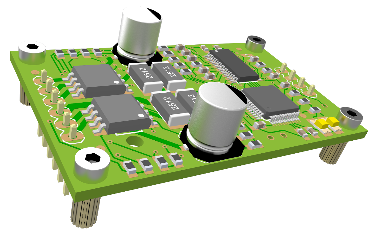 ✖FIMC1V3X ✖FIMC1V3A ✖FIMC1V3X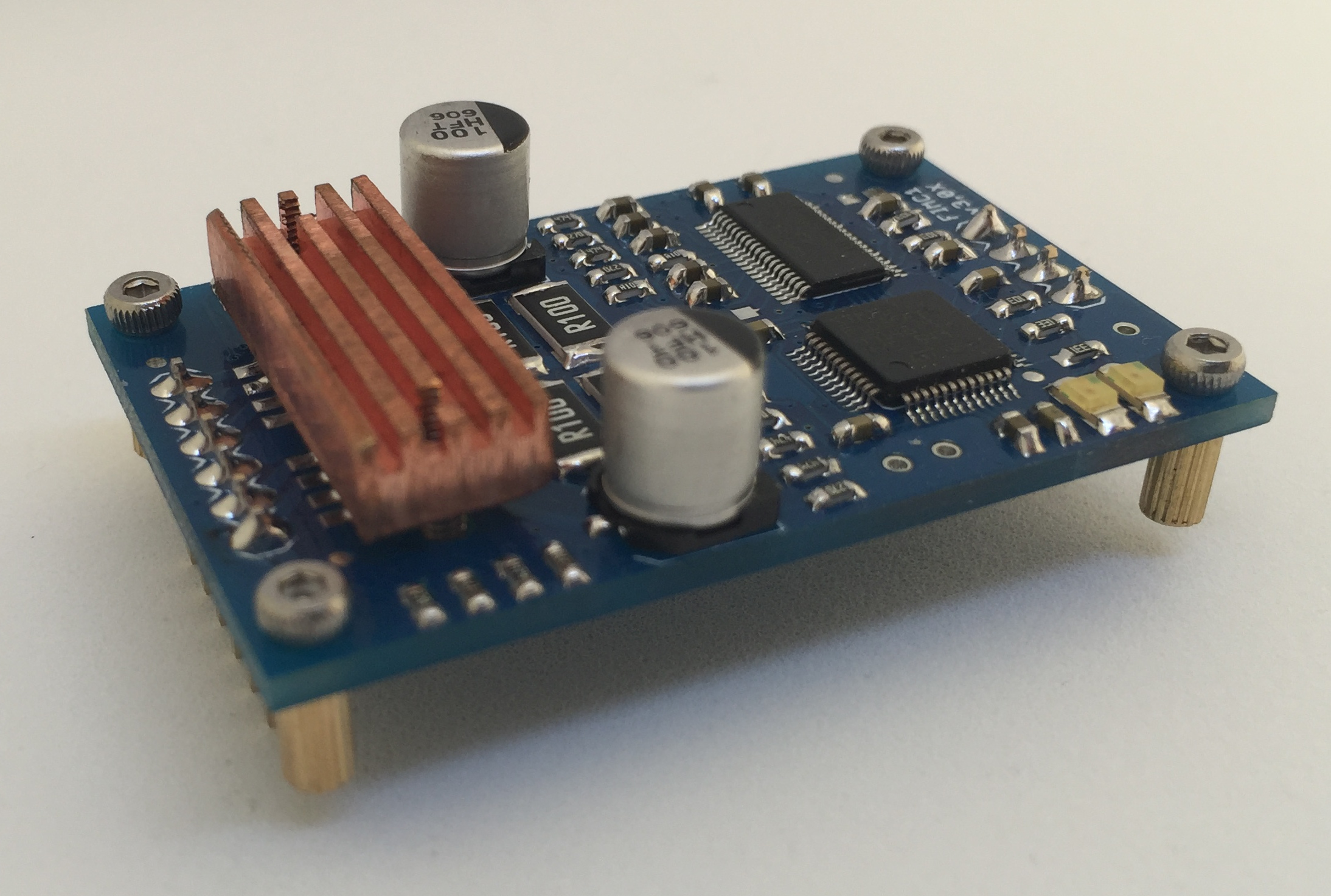 |